
MAS 863: How to Make (Almost) Anything
The on line technique introductions are here. And the source files are down at the bottom of this page.
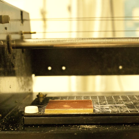
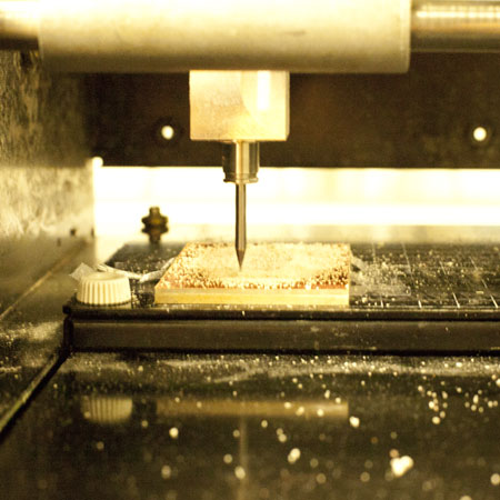
I used Modela to print the board. I double taped the board (Phenolic Paper (FR1)) to another bigger one, and then double taped the bigger one to the left front corner of the Modela panel.
<attention>
1) The bigger board prevented the bit from scratching the machine panel.
2) Both the boards shoud be taped down flat and steady for the later printing.
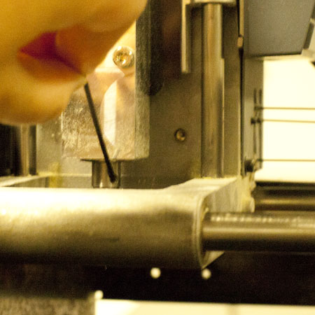
If Modela is in view mode, the bit would move to the back right corner. So when I changed the bit, I first quit the view mode to move the bit in front. There are two screws right on top of the bit. Losening the bit while at the same time holding it to prevent it from falling and being broken.
For milling out the traces, I used 1/64 bit; after that, I changed to 1/32 to cut the outline; Speed, offset should be reset every time. But if you use the Fab Modules, it should be default setting.
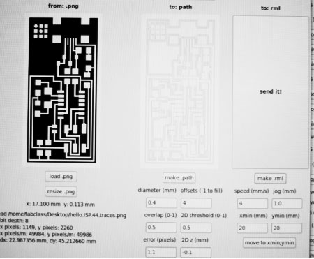
It relates to how to load image, set the parameters of speed and offset. And the origin. Tutorial to user Fab Modues for Modela is here.
The process of using Fab Modules is as follows:
(needs an image of the Fab Modules screenshot)
1) load the png file of traces for Modela, pick up the selection of BIt 1/64; General the path; and follows step 2) to generate the rml file after setting x, y origins.
2)
All the parameters are default except the x, y origins. Before generating the rml file, I had to define my own x, y origins based on where I taped down the board.
3) The next step is setting origins for the bit. First of all, turn on and off the machine to forget the former origin. Secondly, move the bit to x, y origins which i chose on the step 2, by pressing "move x, y, to" button; Then set the z origin, by manually unscrewing the bit, lowering it until it hits the board, and fastening it again.
4) Send the file and confirm
cutting.
5) Load another file. Once 1/32 bit was picked up, other parameters turned to pre-setting.
6) Redo the step 2) to 4).
<attention>
1) before generating the rml, set the x, y origin.
2) before setting x, y, z origions, turn on and off the machine.
3) One thing to try: set Z origin, but don't move x, y to the origin. Try to print. I suppose the machine should do the right thing, because the x, y origin is decided by the rml file.
4) The other thing to try: I should try using command lines to get a better understanding of different parameters.
5) Make sure there are space for the bit to move up and down.
6) Parameters for cutting the traces with 1/64 bit:
tool diameter: 0.4mm
contour: 4
speed: 4 mm/s (2 or 3 mm/s if the bit is new)
depth: -0.2mm
7) Parameters for cutting out the board with 1/32 bit:
tool diameter: 0.8mm
contour: 1
speed: 0.5 mm/s
depth: -1.65mm
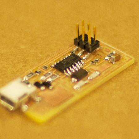
Program the board and make it into a programmer.
<attention>
1. when soldering, from middle to the edge, from botton to top
2. Let solder flow
3. Desolder is a good technique
4. Solder each pin stabelly. The first time I made one pin loose.
5. Set the iron in the middle, around 65 to 70.
Tips from the class.
1. if the board is scratchy, use the sharp steel ruler to clean the bit
2. for desoldering, put a little bit solder on the ironl that way it will help transfer the heat to the braid.
3. What I can share?
4. Tape down the components independently to a strip of transparent tape
5. If the PCB is not leveled perfectly,
6. Plan each week and have fun
7. new endmill is new -> slow the speed a bit
8. power 80, speed 2, try this for vinal cutter for the electronical tape
9. soldering tutorial from Eyal
10. how to debug usb connecting using AVR from Matt's tutorial
11. splitting part of the board instead of desoldering it: Valentin 12. It won't hurt if you deeper the endmill a bit
13. Using command line of Fab Module: Kris
Source File for downloading:
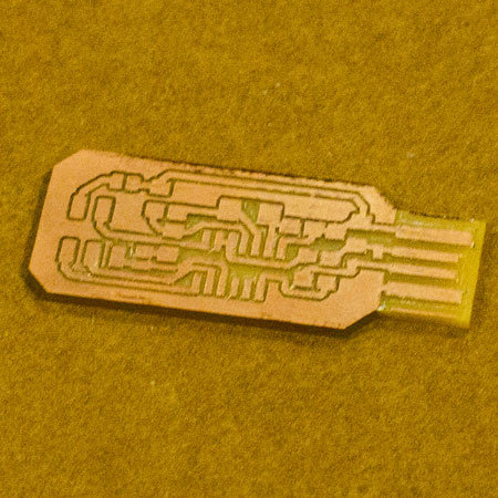
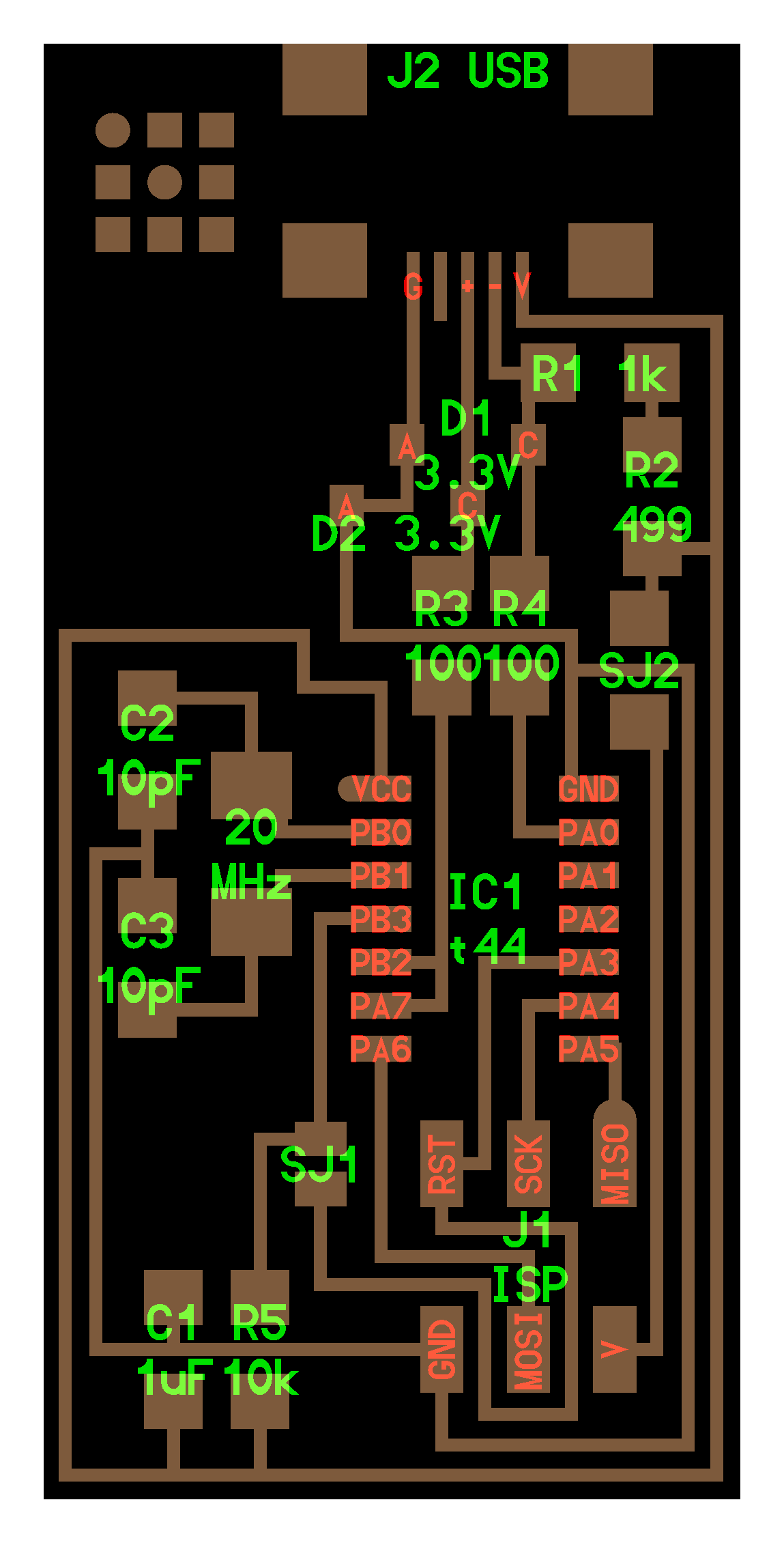
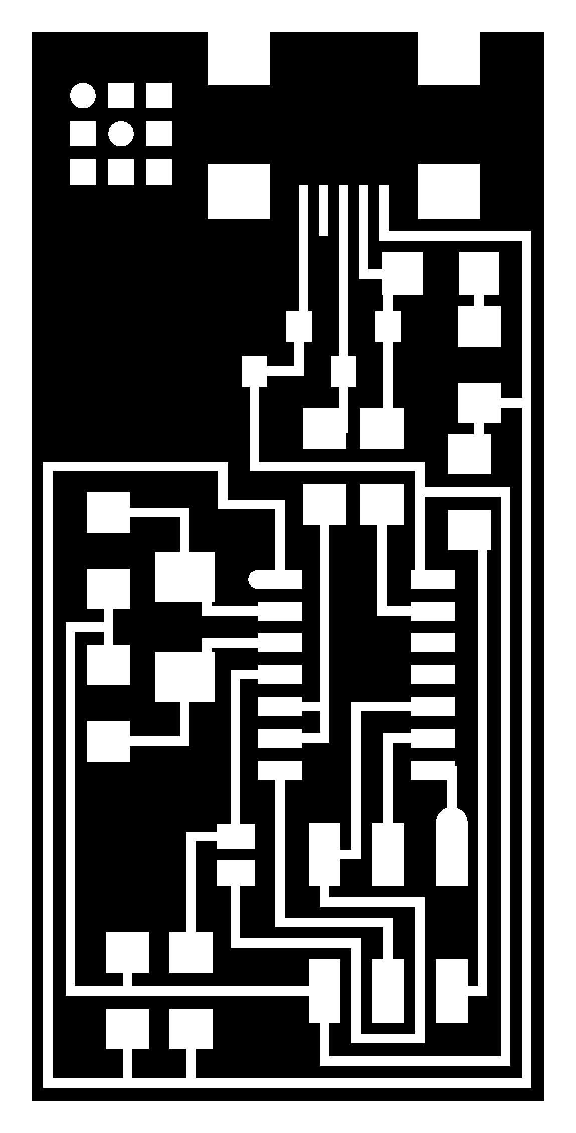
The Board
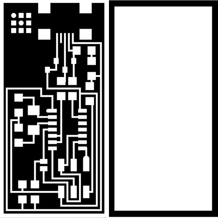
Traces for printing
Cutout lines for printing
Once finish printing and soldering, you need to program the fabISP through another programmer. Under mac, install firmware.
run the lines:
USB power
make clean
make hex
(sudo) make fuse (check programmer in Makefile, may need to repeat)
(sudo) make program
desolder SJ1 and SJ2
make IDC ISP cable, connecting header pin 1 to pin 1